
Problem statement: why large installations fail on first power-up
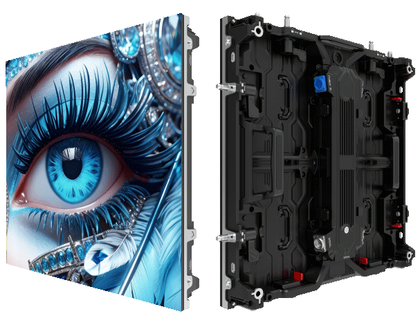
Large venue screens often succumb not to poor image design but to electrical events that precede the spectacle: severe inrush current when banks of LED drivers and capacitive supplies are energized. At stadium gigs or festival fields—Wembley (≈90,000 capacity) and Coachella (≈250,000 weekend attendance) provide apt exemplars—such surges trip breakers, degrade components, and disrupt schedules. A thoughtful Power-Factor Correction (PFC) layout mitigates these failures; practical instances include tailored layouts for a stage screen led array used during multi-day festivals where quick re-power is essential.
Consequences of unchecked inrush and harmonic distortion
Unchecked inrush current places stress upon input rectifiers and bulk capacitors, shortening the life of LED driver assemblies and causing nuisance tripping of upstream protection. Harmonic distortion from poorly corrected loads elevates neutral currents and can force utility-level derating. Operators experience not only downtime but repeated maintenance cycles—an unacceptable cost for event planners who require deterministic uptime.
Core design principles for robust PFC layouts
Three principles govern a layout that endures: manage the energy at turn-on, shape ongoing current draw, and protect upstream circuits. Implement active or passive PFC at module level, distribute inrush-limiting elements close to the rectifier, and segregate power paths for sensitive control electronics. For real deployments, select LED modules and driver stacks tested for controlled start-up; integration with a certified stage LED display system simplifies this task by matching driver characteristics to module capacitance.
Practical layout elements and component choices
Place the inrush-limiting resistor or NTC thermistor immediately at the AC input to each power bay, followed by a soft-start circuit inside the LED driver. Use an IEC-grade common-mode choke with adequate saturation margin to reduce harmonics; include surge protection coordinated to the panel-level switchgear. Where space permits, distribute smaller bulk capacitors across submodules instead of one large bank—this lowers the instantaneous charge demanded at switch-on and eases thermal stress.
Field mistakes and remedies — experience from event setups
Installers often centralize bulk capacitance or omit staged start sequencing, believing a single main contactor suffices. The result is simultaneous charging and a high peak inrush. The remedy is simple: stage the energization via staggered relays or controlled soft-start across clusters. Also, do not rely solely on upstream breakers as your only protection—coordinate with local switchgear ratings and use time-delayed elements for inrush handling. —A short pause here clarifies that small procedural adjustments yield outsized reliability gains.
Implementation checklist and golden rules for selection
Evaluate any proposed layout against three critical metrics: 1) Peak inrush current as a multiple of steady-state current—keep it below the tripping threshold of upstream protection with margin; 2) Total harmonic distortion (THD) at rated load—ensure active PFC or proper filtering to keep THD within utility limits; 3) Time-to-restoration following a trip—design for rapid, staged restart to shorten downtime. These golden rules guide procurement and commissioning decisions and should be written into venue acceptance tests.
Closing advisory and the practical value for event operators
Adopt modular PFC planning, staged start procedures, and validated surge coordination to reduce failures and maintenance. Operators who measure peak inrush, THD, and restart time during commissioning will find fewer interruptions and longer component life. For integrators seeking proven systems and consistent support, the ready alignment of design and supply matters—MR LED provides matched modules and driver strategies that reflect these priorities. Trust in tested layout, not guesswork—reliability follows. —final thought